Today is Friday, January 29, 2021, control of the COVID-19 in Beijing is also promoting the “New Year in place”, the family said the Spring Festival can not visit each other, or each person is fined 1500. It seems to go out as little as possible, if there is nothing to do you’d better stay at home, do more projects, it is also considered to make a contribution to the country.
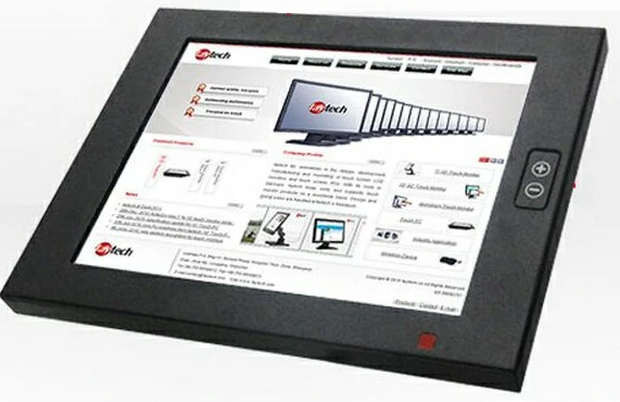
Just a few days ago the serial touch screen STVI056WT-01 arrived, I am ready to use it to upgrade the physical therapy instrument! Now start drawing up a plan and steps.
1. This project is based on the upgrade of the old physical therapy instrument in order to show a better experience to customers.
Add touch screen button function.
Through communication with Arduino serial port, realize the touch screen input to control the output of the product
2. Upgrade the interface, add touch buttons to replace the silicone physical buttons and encoder on the right side of the product.
Make English pictures with the location of the touch buttons.
Import the picture into Tool4.3, make and configure normal buttons, incremental buttons and return value buttons.
3. Connect STVI056WT-01 serial screen and Arduino control board to realize programming control.
Connect the serial screen to the MCU.
Serial communication and control function programming.
Online debugging.
Planning as above, the next step is to do the specific work and solve the problems that will be encountered in the process of doing it.
First, make English pictures with touch button locations
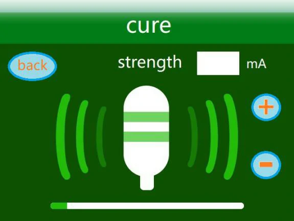
That is, add the necessary buttons in each interface so that these buttons can achieve a reasonable jump between interfaces; there are also incremental buttons to adjust the output intensity instead of the encoder. Two examples are as follows.


Next, import the image into Tool4.3 and create three buttons
This will be done by continuing to watch the related videos and consulting the Tool software instruction manual that you downloaded last time. Of course, the point is to take good notes.
*General button. In Tool4.3 Tools menu Touch Configuration (M), select “Botton”, or click on the button tool at “1” to create a button in the desired location, and fill in the “2” at the “botton effect” for the effective page location, “Page switch” for the jump page, you can complete the button jump function. The same button can be copied on different pages.

**Incremental button. Check “Incremental adjustment” in the Tool4.3 menu Touch Configuration (M) or click on the button tool at “1” in the figure to create a button at the desired location and fill in the “variable memory address” at “2” so that it is the same as the data variable address (0X0888); check the box” after the data automatically upload” at “3” to automatically upload changes to the serial port of the Arduino development board; select “the adjustment way” as “++” or “–“at “4”; in “5”, fill in “adjust the step size” with a step value of 1; in “6”, check the box “long-press quick adjust” to achieve long-press quick adjustment by touching the button.
.webp)
*** Return value button. Check “Return pressed key-value” in the menu Touch Configuration (M) of Tool4.3 tool software, or click on the button tool in the picture as above, create a button in the desired location, and fill in the variable address and key value in the marker as above. Check the box to automatically upload the return value when pressed. The “test” button variable address is 0X0868, and the key value is changed to “0055” (0x0055); the “cure” button variable address is 0X0858, the key value is changed to “0066” (0x0066); the key test serial assistant returns the following values.


Next, connect the serial screen to the MCU.
By experience, a simple connection Arduino development board TX, RX, GND to the serial screen DIN, DOUT, GND, properly “enjoy” a failure. Quickly check the “Datasheet STVI056WT-01” pdf electronic file manual, on page 31 to find the serial screen circuit diagram, found that the screen interface DIN, DOUT signal is RS232. Also, check the “LY-F2 development board circuit diagram”, it is obvious that Arduino development board TX, RX is directly from the microcontroller out of the TTL signal. The reason for failure is obvious, how to solve the problem? By the way, STONE comes with an adapter board, I was looking for a long time, but also has not seen the circuit diagram of the adapter board, so I drew a circuit diagram(manual drawing, because it is relatively simple, I did not start protel99SE, PADS2000, AltiumDesigner 10, Cadence or AUTOCAD2010, etc. software, my computer is slow so that I can save some time). From the drawing, I found a solution to the problem. The adapter board has a MAX232E1 chip, and the TX, RX signal leads out through the jumper, it plays a conversion role so that Arduino development board serial TTL and STVI056WT-01 serial screen RS232 signal can match each other. From the drawing also know that the STONE adapter board DC12V power supply is supplied to the serial screen, the internal MAX232E1, CH340C power supply +5V are provided by the USB, so when using RS232 to serial TTL level conversion, the USB needs to be powered. For the adapter board MAX232 chip, Tin, Rout is 0-5V, while Tout, Rin pin is + – 15V logic. Screenshots are as follows.


As you can see in the picture, the serial screen comes out at RS232 level, and since RS232 is ±15V logic, it is able to transmit farther! Check the “LY-F2 development board circuit diagram”, screenshot as follows.


Then secondly, the serial communication and control functions are programmed.
The Arduino development board was selected to communicate with the STVI056WT-01 serial screen. I have already done serial communication with STVI056WT-01 screen before, and it happens that I used Arduino development board some time ago to finish a project of servo-controlled ticket box automation, and the result was quite good, and it solved the pain point of the demand side in time. The credit goes to Arduino! This is not a lie, because Arduino is not only good, universal, and ready, cheap, do not need a layout, do not need to play the board, do not need to find parts welding, simple development environment, but also comes with a variety of routines, it is very good to use! (This is not advertising for Arduino) The following directly show the real goods.
The “Arduino language instructions” focus on the application of part of the serial port transceiver function instructions excerpted as follows.
Serial port send/receive functions
Serial.begin(speed) : Serial port definition baud rate function, speed means baud rate, such as 9600, 19200, etc.
int Serial.available() : Determine the buffer status.
int Serial. read(): Read the serial port and return the received parameters.
Serial.flush() : flushes the buffer.
Serial.print(data) : Output data from the serial port.
Serial.println(data) : Output data with carriage return.
In the 232-page “Getting.Started.with.Arduino” pdf full English electronic document, there is a more detailed description of the instructions, screenshot saved below.

As you can see, the Arduino can support a serial screen baud rate of 115200, which is also the highest value that can be chosen for this time.


After testing with the serial assistant, the two print functions above transmit in character form. For example.
Serial.print(75,HEX);
The string transmitted is “4B”, which is the ASCII value of the characters “4” and “B” (0x34, 0x42); therefore, serial. print() function, whether string or data, are sent ASCII, not suitable for command transmission!
Fortunately, in Arduino 1.0.5, under the menu help, click on the “Reference” item, it will pop up the function description of each function displayed by category, among which the latest serial function is serial. write(Val), screenshot as follows.

The function transmits the binary code, and the test transmission is correct and can jump pages correctly; as follows.

Moreover, the serial.write(Val) function supports writing hexadecimal directly, such as serial. write(0x80), which compiles and uploads successfully, as shown below. Therefore, the serial write() function sends the value VAL in binary and the string in ASCII.


For the Arduino development environment, just run the arduino.exe directly under the Arduino-1.0.5 package directory.

After double-clicking, wait for a while, the following startup screen will appear


.jpg)


