Without a detailed analysis of the various operating commands issued by the control unit to complete different instructions, this article will take an in-depth look at the relationship between command cycles, machine cycles, clock cycles (ticks) and control signals.
Control the function of the unit
Micromanipulation command analysis
Previously, I explained the micro-operation instructions of the value taking period and the interlocation period
(1) Execution cycle
1. Addition instructions. Addition has too much uncertainty, such as operands can be in registers, accumulators, main memory, etc., these micro-operation commands are not the same, the following assumptions a premise.
Premise: Suppose an operand is in the accumulator, an operand is in the main memory A unit, and the operation result is sent to the accumulator, please write out the specific micro-operation instructions.
Idea: First take the number from the main memory, and then add the contents of the accumulator ACC and send it to the ACC. The sequence of microprograms is as follows:
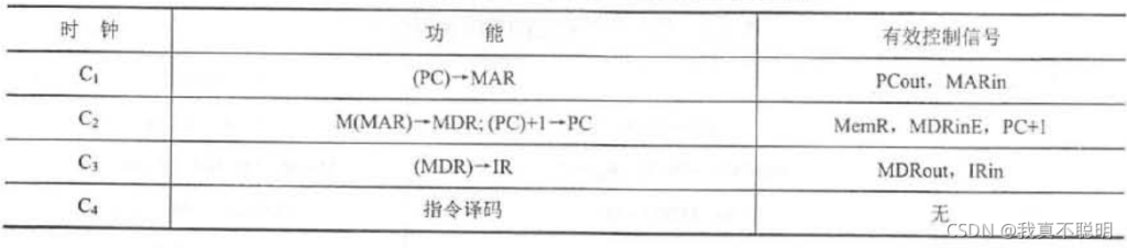
Ad(IR)-> MAR // Feeds the address code of the instruction into the main memory address register
1->R // boot memory read
M(MAR)->MDR // The content (operand) in the main memory unit referred to by MAR is read to MDR through the data bus, where it can be written as M(MAR)->BUS->MDR, where BUS can be not added, but if it is a bus connection, it needs to be written.
(ACC)+(MDR)->ACC // sends an add command to the ALU to add the contents of the ACC and the MDR, and the result is stored in the ACC
2. Memory instruction
Premise: It is assumed that the results of the above accumulator ACC are stored in the main memory A geological unit.
Microprogram instructions:
Ad(IR)-> MAR // Feeds the address code of the instruction into the main memory address register
1->W // boot memory write
(ACC)-> MDR // Sends the contents of the accumulator to the MDR
(MDR)->M(MAR) // Writes the contents of the MDR to the referred primary memory unit
(2) Interruption period
After the execution cycle ends, the CPU needs to query for events that have requested an interrupt, and if so, enter the terminal cycle. Where are the breakpoints saved by interrupt hidden instructions? How do I find a Terminal Services program portal? Only by solving these two problems can you write out the micro-instruction sequence.
Premise: Suppose the program breakpoint is saved to the ‘0’ cell of the main memory, and the hardware vector method is used to find the ingress address. The sequence of microinstructions for the interrupt cycle is as follows:
0-> MAR // Feeds the address of the main memory ‘0’ unit into the main memory address register
1->W // boot memory write
(PC) – > MDR // Feeds the contents of the PC (program breakpoints) into the master data register
(MDR)->M(MAR) // Writes the contents of the main memory data register to the main memory cell indicated by MAR
Vector Address – > the output of the vector address forming part to the PC
0-> ENT //off interrupt to allow the interrupt trigger to be cleared
If the breakpoint is not stored in primary memory, but in the stack, then you need to change 0-> MAR to SP-1->SP and (SP)->MAR
Control the function of the unit
The external characteristics of the control unit
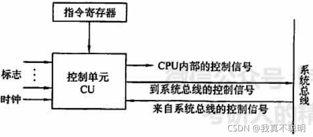
Enter the CU as follows:
1) Instruction Register (IR). The opcode of the instruction is fed to the CU for decoding.
2) Logo. Sometimes the control unit needs to generate the corresponding control signal according to the result of the up-adjustment instruction. Because the ‘flag’ is also the input signal of the control unit.
3) Clock. How much time does each operation take? What is the order in which each operation is executed? How to solve it? This uses a clock signal, which is controlled by a clock pulse.
4) Control signal from the system control bus. Input to signals such as interrupt requests, DMA (Direct Memory Access Direct Memory Access) requests, etc.
The output CU is as follows:
1) Control signal in the CPU. It is mainly used for transferring between CPU registers and controlling ALU to achieve different operations.
2) The control signal sent to the system control bus. Input of signals such as interrupt requests, DMA requests, etc.
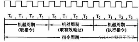
Multi-stage timing system
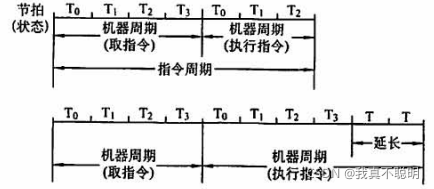
In fact, the speed of the machine is not only related to the main frequency, but also to the clock cycles contained in the machine cycle and the number of machine cycles contained in the instruction cycle. Machines with the same frequency run at different speeds due to the different number of clock cycles contained in the machine cycles. Machine cycles are faster for machines with fewer clock cycles.
The effective control signal ↑ corresponds to each beat
Control mode
Since the instruction cycle of a machine instruction is composed of an unequal number of CPU cycles, the number of CPU cycles reflects the complexity of the instruction action, that is, the number of operating control signals. For a CPU cycle, there are also problems with the number of operating control signals and the order in which they appear. Taken together, these two situations illustrate that each instruction and each operation of the control signal takes a different time. The method of controlling the timing signal of different operation sequences, called the control mode of the controller, is commonly used in four ways: synchronous control, asynchronous control, joint control and manual control, and its essence reflects the timing mode of the timing signal.
(1) Synchronous control mode
The way in which any instruction or the execution of any micro-operation in an instruction is controlled by a timing signal that is determined in advance and has a uniform reference timescale is called synchronous control. There are three specific scenarios
1) Adopt the machine cycle of completely unified cycle time (fixed length method). This scheme is characterized by the longest sequence of micro-operations and the most cumbersome micro-operations as the standard, taking a completely uniform, with the same time interval and the same number of beats as machine cycles to run different instructions, as shown in the figure below
This way for simple operation of most of the instructions is a waste of time, such as 4 operations A, B, C, D, respectively need 1s, 2s, 1s, 2s, and the machine cycle needs to be set to 20s, for ABCD is a waste
2) Machine cycles with different beats (indefinite length). This scheme can vary in the number of beats per machine cycle, as shown in the figure below, some instructions are less operational, and the machine cycle contains only 3 beats. Some micro-instructions are complex to operate, and they can be solved by extending the machine cycle, that is, increasing the beat

3) The method of combining central control and local control is adopted. This scheme arranges most of the instructions of the machine to be completed in a uniform, shorter machine cycle, called central control; Some of the operations in the few complex instructions are completed by local control, such as multiplication, division, and floating-point operations. The following figure shows the timing relationship between central control and local control.
 The function and working principle of the controller")
For the local control beat, its width is the same as the central control beat width, and the local control beat as a continuation of the central control machine beat, inserted into the central control of the execution cycle, so that the machine works at the same rhythm, to ensure the synchronization of local control and central control.
Taking the multiplication instruction as an example, the first machine cycle uses a centrally controlled beat control to take the command operation, and then still uses the central control
, , the beat to complete the operation of taking out the operands memory and sending it to the register, and then turn to local control, and use the local control beat to complete the operation of repeating the addition and shifting.
(2) Asynchronous control mode
The asynchronous control mode has no reference time slot signal, no fixed cycle beats and strict clock synchronization, and as much time is used to execute each step of the instruction and each operation. The timing of the micro-operation in this way is controlled by a special response line, that is, when the CU issues a control signal to perform a micro-operation, wait for the execution component to complete the operation and send back the “answer” signal, and then start a new micro-operation, so that the CPU has no idle state, but because of the need to use the response circuit, its structure is more complex than the synchronous control mode.
Purpose: Asynchronous control is generally used for transfer control between the host and the I/O device, so that the high-speed host and the slow I/O device can set the timing system according to their respective needs.
(3) Joint control mode
The joint control mode makes a compromise between the synchronous control mode and the asynchronous control mode, which adopts the same synchronous control mode for most of the micro-operations of various instructions, and the asynchronous control mode adopts the small part of the asynchronous control mode.