STM32 based bicycle intelligent wireless anti-theft alarm
1 Introduction
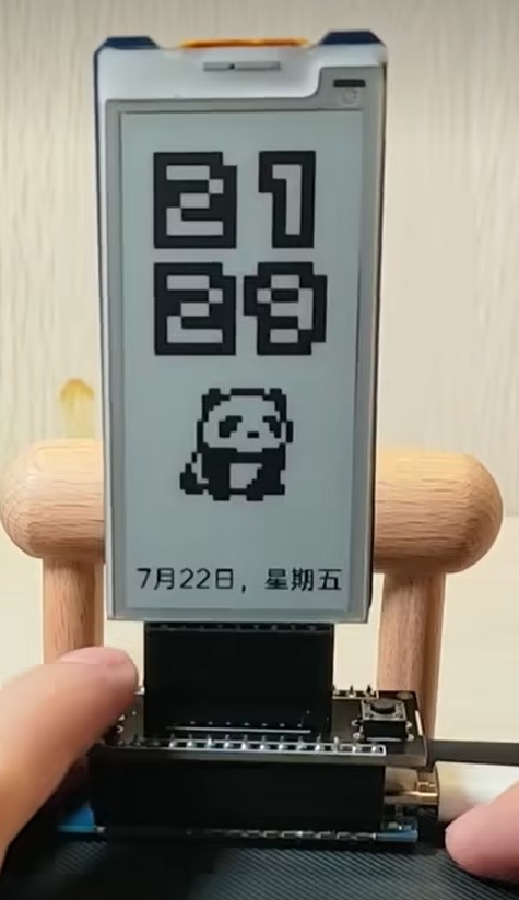
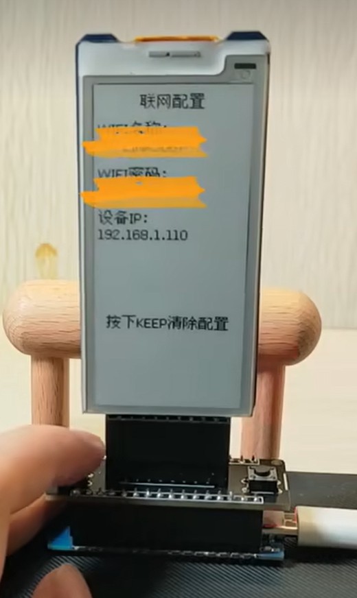
Using the ESP32C3 development board of HZU, we designed a detachable desktop mode screen ornament, which is networked through wifi and can realize four modes of displaying time, weather, ancient poems and pictures. Switching and updating between different modes are realized by pushing buttons.
2 Main Devices
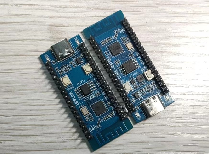
ESP32C3 development board
Ink screen module
MOSFET-N+AO3400A
Pushbutton micro switch 664.3
PCB socket_2.54_2x8/16P vertical
3 Realization effect

4 Implementation principle
4.1 Hardware part
Ink screen module
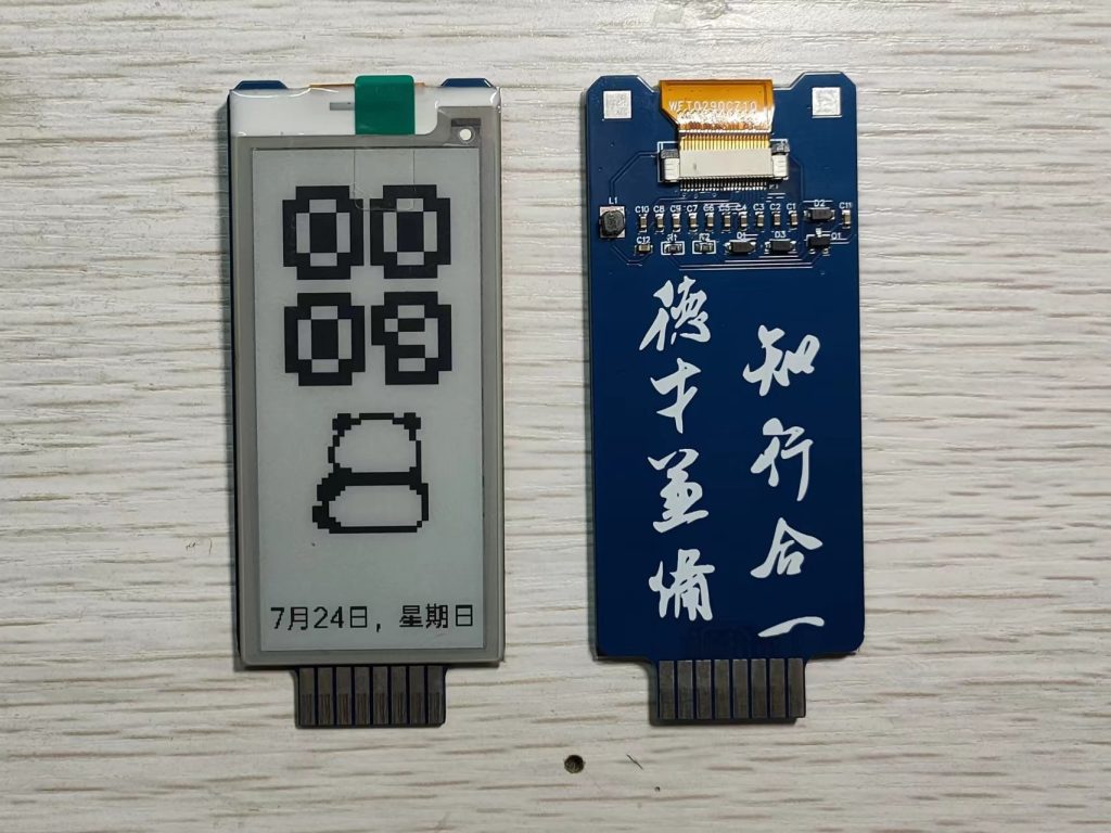
Using a 2.9-inch ink screen, the price of a single piece of about 15
Project in the software side of the drive ink screen using the GxEPD2 library, in the GxEPD2 library to select the appropriate for the model can be. As shown below.
GxEPD2_BW<GxEPD2_290, GxEPD2_290::HEIGHT> display(GxEPD2_290(/CS=5/ 7, /DC=/ 4, /RST=/ 5, /BUSY=/ 6)); // screen model 1
GxEPD2_BW<GxEPD2_290_T5, GxEPD2_290_T5::HEIGHT> display(GxEPD2_290_T5(/CS=5/ 7, /DC=/ 4, /RST=/ 5, /BUSY=/ 6)); // Screen model 2
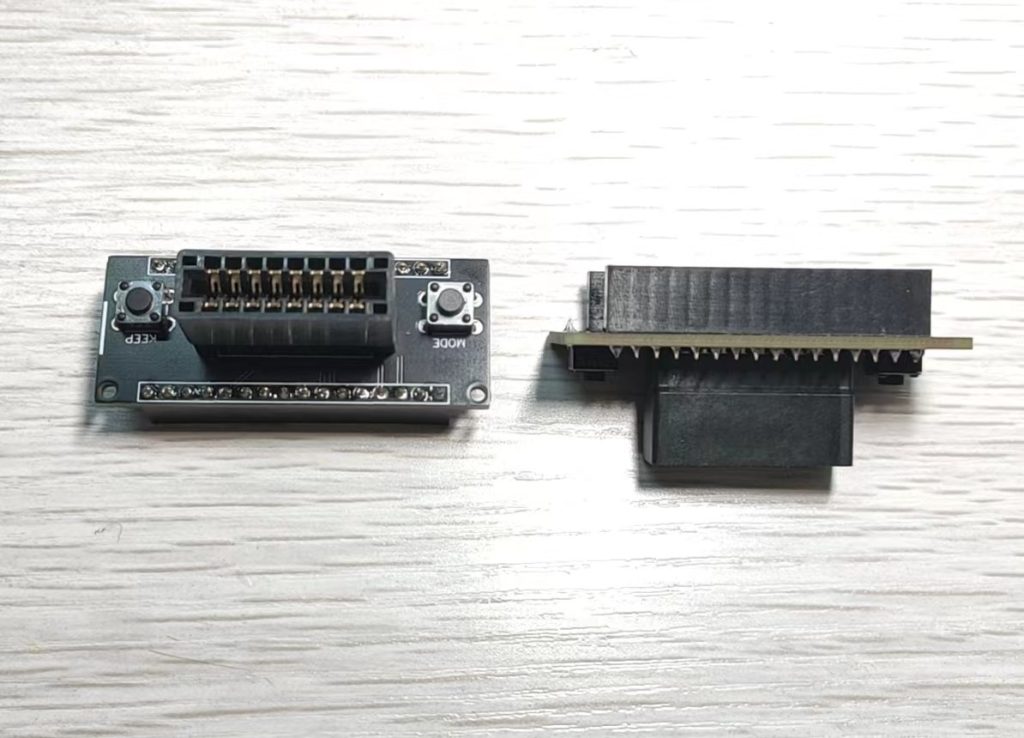
The base module mainly serves as a connection between the development board and the ink screen module.
Solder the PCB socket to unplug the ink screen module, solder the female to connect with the ESP32C3 development board, and solder the button to control the display.
ESP32C3 development board

To use the ESP32C3 development board from HZU, you can buy either the classic model or the minimalist model.
The classic model is more convenient, because using the simple model will pay attention to more technical details, easy to meet the pit.
The pins can be soldered upwards, because the pins are connected to the mother of the row, and it is very convenient to unplug them after this project to do other projects.
4.2 Software part
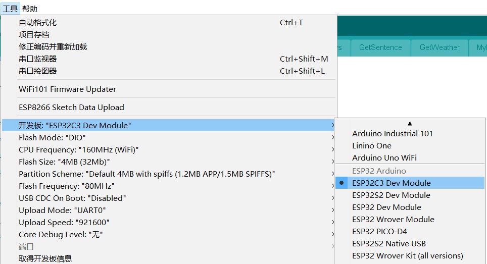
Programming software Arduino
Programming software Arduino, environment configuration reference online information.
Development board add
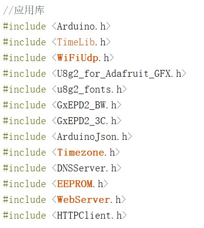
The libraries used in this project are
- ArduinoJson library: parse Json data, the weather, ancient poems, quotes and other information in the project are obtained through some APIs and saved in the returned json data.
- GxEPD2 library: drive the ink screen
- Timezone library: the need to obtain the clock through NTP
- U8g2 library: image display library
The library can be searched and downloaded in Project->Load Libraries->Manage Libraries.
5 Part of the core firmware code
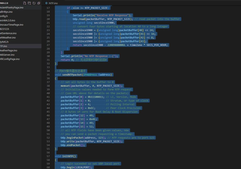
// wifi connection UDP setting parameters
WiFiUDP Udp;time_t getNtpTime() // get time by NTP
{
IPAddress ntpServerIP; // NTP server’s ip address
while (Udp.parsePacket() > 0)
; // discard any previously received packets
// Serial.println(“Transmit NTP Request”);
// get a random server from the pool
WiFi.hostByName(ntpServerName, ntpServerIP);
sendNTPpacket(ntpServerIP);
uint32_t beginWait = millis();
while (millis() – beginWait < 1500)
{
int size = Udp.parsePacket();
if (size >= NTP_PACKET_SIZE)
{
Serial.println(“Receive NTP Response”);
Udp.read(packetBuffer, NTP_PACKET_SIZE); // read packet into the buffer
unsigned long secsSince1900;
// convert four bytes starting at location 40 to a long integer
secsSince1900 = (unsigned long)packetBuffer[40] << 24;
secsSince1900 |= (unsigned long)packetBuffer[41] << 16;
secsSince1900 |= (unsigned long)packetBuffer[42] << 8;
secsSince1900 |= (unsigned long)packetBuffer[43];
return secsSince1900 – 2208988800UL + timeZone * SECS_PER_HOUR;
}
}
Serial.println(“No NTP Response :-(“);
return 0; // return 0 if unable to get the time
}// Send a request to the NTP server
void sendNTPpacket(IPAddress &address)
{
// set all bytes in the buffer to 0
memset(packetBuffer, 0, NTP_PACKET_SIZE);
// Initialize values needed to form NTP request
// (see URL above for details on the packets)
packetBuffer[0] = 0b11100011; // LI, Version, Mode
packetBuffer[1] = 0; // Stratum, or type of clock
packetBuffer[2] = 6; // Polling Interval
packetBuffer[3] = 0xEC; // Peer Clock Precision
// 8 bytes of zero for Root Delay & Root Dispersion
packetBuffer[12] = 49;
packetBuffer[13] = 0x4E;
packetBuffer[14] = 49;
packetBuffer[15] = 52;
// all NTP fields have been given values, now
// you can send a packet requesting a timestamp:
Udp.beginPacket(address, 123); // NTP requests are to port 123
Udp.write(packetBuffer, NTP_PACKET_SIZE);
Udp.endPacket();
}void initNTP()
{
// Login suceeded so set UDP local port
Udp.begin(LOCALPORT);
// Set the time provider to NTP
setSyncProvider(getNtpTime); // synchronize the time
}