1. Programme design
1.1. Design requirements
Design an electronic stopwatch with a 4-digit digital tube displaying the time from 00.00 seconds to 99.99 seconds, a total of 100 seconds. The time is modified using the keys, key one is pressed to add one second, key two is pressed to subtract one second, key three is pressed to set zero and key four starts or pauses the timer.
1.2. Programme discussion
This system uses the STC89C51RC as the main control and uses a 4-bit common negative digital display to avoid using four separate digital tubes which would cause the microcontroller IO ports to be inadequate and waste resources. The microcontroller drives the 4-bit common negative digital tube with two 74HC573 chips, when the enable terminal is high, the output will change with the data input. When enable is low, the output will latch onto the established data level. The output control does not affect the internal operation of the latch, the original data can be held and even when the output is turned off, new data can be set in. 74HC573 can drive large capacitors or low impedance loads and can interface directly with the system bus and drive the bus without the need for an external interface. The time setting can be satisfied using four individual keys.
2. Hardware design
2.1. Main controller
The STC89C51RC is an 8051 core ISP (In System Programming) chip with a maximum operating clock frequency of 80MHz and a 4KB Flash read-only program memory that can be repeatedly erased 1000 times. The device is compatible with the standard MCS-51 instruction system and the 80C51 pin structure. The chip integrates a general-purpose 8-bit central processor and an ISP Flash memory unit, and has the In System Programming (ISP) feature.
The STC89C52RC series microcontrollers are single clock/machine cycle (1T) compatible 8051 core microcontrollers, a new generation of high speed/low power 8051 microcontrollers with a new pipeline/streamlined instruction set architecture and an integrated MAX810 dedicated reset circuit.
Features of the STC89C51 family of microcontrollers.
(1) Enhanced 1T pipelined/streamlined instruction set architecture 8051 CPU
(2) Operating voltage: 3.4V-5.5V (5V MCU / 2.0V-3.8V (3V MCU)
(3) Operating frequency range: 0 – 35 MHz, equivalent to 0 – 420 MHz of the common 8051.
(4) User application space 12K / 10K / 8K / 6K / 4K / 2K bytes
(5) On-chip integrated 512 bytes RAM
(6) General purpose I/O ports (27/23), after reset: quasi-bidirectional / weak pull-up (common 8051 conventional I/O ports) can be set to four modes: quasi-bidirectional / weak pull-up, push-pull / strong pull-up, input only / high resistance, open-drain each I/O port can drive up to 20mA, but the whole chip should not exceed 55mA maximum
(7) ISP (in-system programmable)/IAP (in-application programmable), direct user program download via serial port (P3.0/P3.1) without dedicated programmer, one piece can be completed in seconds
(8) EEPROM function
(9) Watchdog
(10) Internal MAX810 dedicated reset circuit (external reset circuit can be omitted if external crystal is below 20M)
(11) Clock source: external high precision crystal/clock, internal R/C oscillator. The user can choose whether to use the internal R/C oscillator or the external crystal/clock when downloading the user program. The frequency of the internal R/C oscillator is 5.2MHz to 6.8MHz at room temperature, and the internal clock can be used when accuracy is not required, because of the temperature drift, please select 4MHz to 8MHz.
(12) Two 16-bit timers/counters are available.
(13) 2 external interrupts, falling edge interrupt or low level triggered interrupt, power down mode can be woken up by external interrupt low level triggered interrupt
(14) PWM (4 channels) / PC A (programmable counter array), also can be used to implement another 4 timers or 4 external interrupts (rising edge interrupt / falling edge interrupt are supported)
(15) The STC89Cc516AD has an ADC function. 10-bit precision ADC, 8 channels in total
(16) Universal asynchronous serial port (UART)
(17) SPI synchronous communication port, master/slave mode
(18) Operating temperature range: 0 – 75°C / -40 – +85°C
(19) Package: PDIP-28, SOP-28, PDIP-20, SOP-20, STC89C52RC series microcontrollers are true watchdogs, default is off (cold start), start PLCC-32,TSSOP-20 (ultra small package, on order) can not be turned off after moving, external watchdogs can be omitted. This series of microcontroller P4 port address is E8H, and there are two additional external interrupts, P4.2/INT3, P4.3/INT2.
2.2. Crystal and reset module
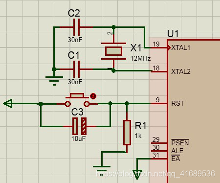
The crystal circuit uses a 12MHz crystal and two 30PF capacitors. In the reset circuit, a key level reset is used with a 10uF capacitor and a 10k resistor. when the system is in a normal state, if there is a high level on the RST pin and it is maintained for 2 machine cycles, the CPU responds and resets the system. The crystal oscillator and reset circuit is shown in the diagram on the right.
2.3. Keypad Module
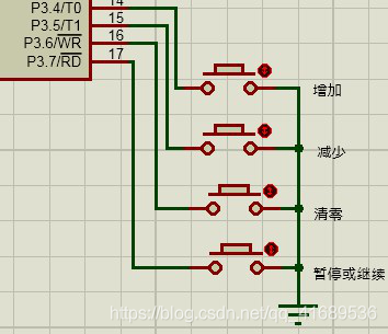
The system is designed with four independent input keys, which are directly connected to the P3 port of the microcontroller. When the key is not pressed, the microcontroller detects that the pin is high; when the key is pressed, the microcontroller detects that the pin is low and executes the corresponding program. So by detecting the change in state of the corresponding port, it is possible to detect if a key is pressed. The keyboard circuit is shown in the diagram below.
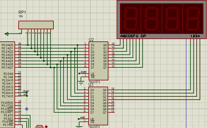
The digital tube uses a four-segment common negative digital tube, and the segment selection and bit selection of the digital tube are controlled by two 74HC573 blocks respectively.
When the LE terminal of the first 74HC573 is high and the LE terminal of the second 74HC573 is low, the P0 port controls the segment selection and the digital tube can display the content. Displaying numbers can be coded to ten numbers from 0 to 9, and then the numbers to be displayed can be sent to the P0 port through this code. When the LE terminal of the second 74HC573 is high and the LE terminal of the first 74HC573 is low, the P0 port controls the bit selection and can control the digital tube to display the first few digits. As the P0 port is used as an I/O port, the field effect tube inside the P0 port is cut off and the output is open drain, a pull-up resistor must be connected to have a high level output. In this system, the P0 port is connected to a 10K pull-up resistor. The display circuit is shown in the figure below.
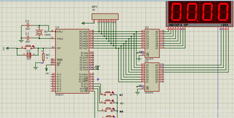
3. System Simulation Diagram
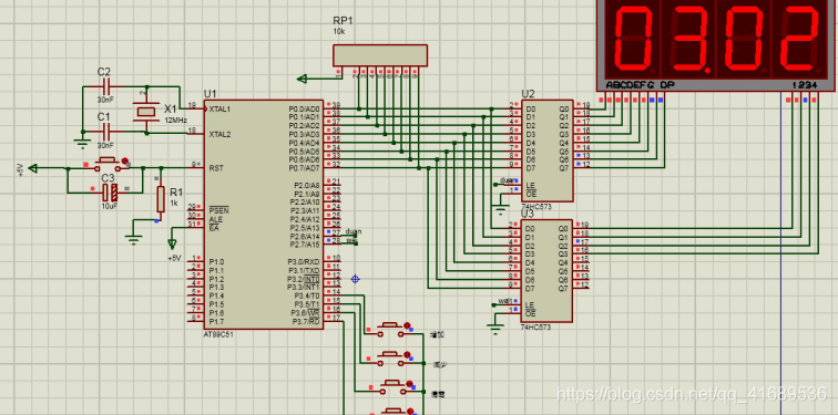
The system simulation diagram drawn using Proteus simulation software is as follows.

4. Software design
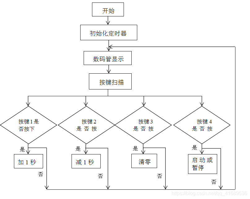
In Keil software, C51 programming is used to implement the function of electronic stopwatch. The program includes the main function, delay function, timer hmi touch screen initialization, digital tube display, keyboard scan and interrupt service program. The program is executed from the main function, initialising the timer first, and then keeps cycling through the calls to the digital tube display and keyboard scan functions.
4.1. Software flow diagram
5. System verification and analysis
The following figure shows the effect of simulation.
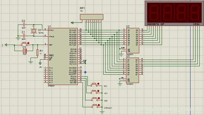
The following diagram shows the effect of starting the simulation. The current display indicates that the timing has reached 3.02 seconds.
The following figure shows the effect of the upcoming timing to 99.99 seconds. After reaching 99.99 seconds, all of the time will be cleared.
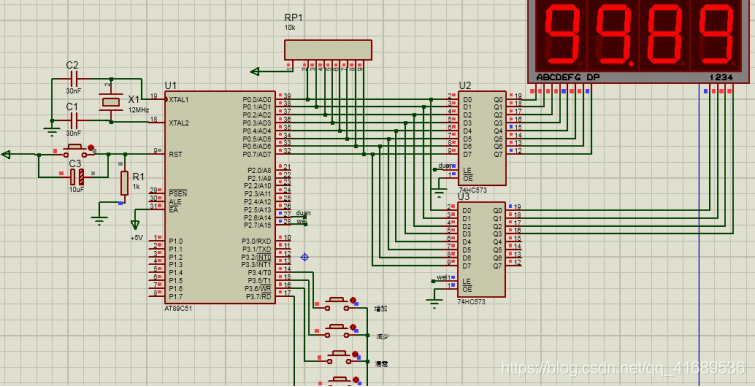
As can be seen from the above Proteus simulation, the system achieves all the basic functions and achieves the desired results. However, during the simulation process, the timing accuracy is not accurate enough and slower than a normal stopwatch due to the simulation software running with a certain delay. In addition, the counting time of the two digital tubes after the decimal point was so fast that it was difficult for the human eye to distinguish the changes of the digital tubes.
6. Conclusion
This design is based on a digital stopwatch controlled by a microcontroller, the cost of the system is low, but the practical value is high and the technology used is more stable and mature, in addition, the application requirements of the system are not very high. Through this stopwatch design, we have learned a lot of knowledge, but also learned a lot of ways to think about the problem, but also to improve the analysis of problems, problem-solving ability.