The basic composition and implementation of the controller
The composition of the controller
Instruction
Parts The main task is to complete the command analysis instructions, the instruction parts include:
! [Basic Composition of the Controller] (C:\Users\hp\Desktop\The basic components of the controller .png) (1) Program counter
(2) Instruction register
(3)
Instruction decoder is also known as an operands decoder
, or instruction function analysis interpreter. The instructions in the staging instruction register can only be recognized after the operation part of the program is decoded to identify what kind of instruction it is, and generate the corresponding control signal to provide to the bit operation signal generator. hmi display lcd
(4) Address forming components Address
forming components according to the different addressing methods of the instruction, the formation of the effective address of the operand, in the micro, minicomputer, can not set a special address to form the component, but the use of the operator to carry out the operation of the effective address.
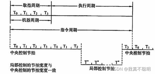
Timing components Timing
components can generate a certain timing signal to ensure that the various functional parts of the machine rhythmically transmit, process and store information. The timing components include:
(1) Pulse Source The
pulse source is used to generate a clock signal with a certain frequency and width, providing a reference signal for the whole and it. (Generally use quartz crystal oscillator) (2)
start-stop control logic
Only after the computer is started by the start-stop control logic, the pulse in the note is allowed to enter. It guarantees that the first pulse and the last pulse of the output at stop are full pulses.
(3) Tick signal generator Beat
signal generator (pulse splitter). The pulse signal generated by the pulse source passes through the tick signal generator to generate the beat signal in each of its cycles.
Micro operation signal generator
The removal and operation of a single instruction can be decomposed into many basic operations, and this most basic inseparable operation becomes a bit operation. Also known as a control unit (CU). Different machine instructions have different sequences of microoperations.
Terminal
control logic is hardware logic used to control interrupt handling.
The hardware implementation method of the controller
The core of the controller is the operating signal generator (control unit CU).
The bit operation control signal is formed by the decoding signal provided by the command part, the timing signal provided by the timing is not seen, and the status and conditions feedback by the controlled functional components.
According to the different ways of operating the control signal generated, the controller is divided into:
Combinatorial logic
The control unit CU is a complex tree network consisting of gate circuits. There are only a few jumbo machines and RISCs (Reduced Instruction Set Computer, Chinese Reduced Instruction Set Computer. The feature is that the format of all instructions is the same, the instruction period of all instructions is the same, and the pipeline technology is used. In order to pursue high speeds, the machine still uses a combinatorial logic controller.
Storage
logic type microprogram controller, using storage logic to achieve, that is, the bit operation signal code, so that each instruction is converted into a microprogram stored in a special memory. Instructions are executed more slowly than combinatorial logic controllers.
Combinatorial
logic and storage logic combination controller is called a programmable logic array (PLA) controller